
What is the CE 65 encoder?
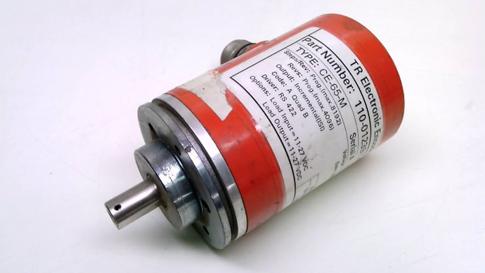
The CE 65 is an industrial absolute rotary encoder manufactured by TR Electronic. It is designed to acquire angular position data and condition measuring data for controllers that adhere to the DIN 19258 standard. This device is a component of industrial motion control systems, not a consumer electronics product. It provides precise, non-volatile position feedback even after power loss.
Absolute encoders like the CE 65 report the exact shaft position at any given moment. Unlike incremental encoders, which only track relative movement, the CE 65 delivers a unique digital code for every shaft angle. This capability is essential in applications where immediate position awareness is required upon startup, such as in robotics, CNC machinery, and automated assembly lines.
The encoder supports multiple communication protocols, allowing it to integrate with various industrial networks. Common interfaces include SSI (Synchronous Serial Interface), BiSS, and proprietary protocols like Interbus-S. This multi-protocol support ensures compatibility with a wide range of PLCs and motion controllers, making it a flexible choice for diverse industrial environments.
The CE 65 is built for durability in harsh industrial settings. It typically features a robust metal housing and high IP (Ingress Protection) ratings to resist dust, moisture, and vibration. These physical characteristics ensure reliable operation in environments where standard electronic components might fail.
KeyTakeaways items
- The CE 65 is an industrial-grade absolute encoder from TR Electronic.
- It provides precise, non-volatile position feedback for motion control systems.
- The device supports multiple protocols, including SSI, BiSS, and Interbus-S.
- It is designed for durability and reliability in harsh industrial environments.
Key Technical Specifications
The CE 65 encoder is an absolute rotary encoder designed to acquire angular motion and condition measuring data for controllers compliant with DIN 19258 standards. Engineers must verify specific pinouts and electrical characteristics against the official TR Electronic datasheet before integration.
Power requirements for the CE 65-M typically operate on a 10–30 V DC supply, though this varies by specific model variant. The encoder supports multiple interface protocols, including CANopen, DeviceNet, and Interbus-S, allowing flexibility in PLC connectivity. Resolution options generally range from 12-bit single-turn to multi-turn configurations with up to 4,096 revolutions, providing precise position feedback for industrial automation tasks.

Verify that your PLC or controller supports the specific bus protocol (CANopen, DeviceNet, or Interbus-S) selected for your CE 65 model.
Determine if single-turn or multi-turn absolute positioning is required. Select a model with sufficient revolution counts (e.g., 4,096) if battery backup is not used.
Ensure your power supply matches the encoder's voltage range (typically 10–30 V DC) and current draw limits to prevent signal instability.

Common CE 65 variants and interfaces
CE 65 Encoder Review works best as a clear sequence: define the constraint, compare the realistic options, test the tradeoff, and choose the path with the fewest hidden costs. That order keeps the advice usable instead of decorative. After each step, pause long enough to check whether the recommendation still fits the reader's actual situation. If it depends on perfect timing, unusual access, or a best-case budget, include a simpler fallback.
| Factor | What to check | Why it matters |
|---|---|---|
| Fit | Match the option to the primary use case. | A good deal still fails if it does not fit the job. |
| Condition | Verify age, wear, and service history. | Hidden condition issues erase upfront savings. |
| Cost | Compare purchase price with likely upkeep. | The cheapest option is not always the lowest-cost option. |
Where to buy CE 65 encoders
Procuring the TR Electronic CE 65 encoder requires distinguishing between new OEM stock and verified used inventory. New units offer full manufacturer warranties and traceability, which is critical for compliance-heavy industries. Used encoders, often sourced from surplus dealers or marketplaces, provide a cost-effective alternative for maintenance and repair (MRO) workflows where budget constraints outweigh the need for pristine condition.
For immediate availability, industrial surplus specialists and B2B marketplaces frequently stock the CE 65-M variants. These channels often guarantee functional testing before dispatch, reducing the risk of receiving defective hardware. However, lead times can vary significantly depending on the specific interface protocol (e.g., Profibus-DP, CANopen, or SSI) and shaft configuration required.
Amazon serves as a primary retail channel for standalone CE 65 units, particularly for engineers needing rapid delivery. The marketplace aggregates listings from various industrial suppliers, offering a convenient way to compare interface types and voltage specifications. Below are current available CE 65 encoder listings on Amazon, focusing on models with Profibus-DP and CAN interfaces.

As an Amazon Associate, we may earn from qualifying purchases.
When selecting a supplier, verify the output signal type and electrical specifications against your PLC or controller’s requirements. The CE 65 series supports various output codes, including TTL, HTL, and EnDat. Ensuring compatibility with your system’s voltage levels (typically 10-30V DC) and current consumption limits is essential to prevent hardware damage.
Installation and maintenance tips
Proper installation of the CE 65 encoder is critical for maintaining signal integrity and preventing premature mechanical failure. The unit is designed for DIN 19258 standard mounting, ensuring compatibility with most industrial control systems. Secure mounting prevents vibration-induced misalignment, which can distort angular motion data.
Mechanical Alignment and Mounting
Begin by securing the encoder to the shaft using the provided coupling. Ensure the shaft is perfectly aligned to avoid radial and axial loads that exceed the bearing limits. Use a dial indicator to check for runout before tightening the set screws. Misalignment is the leading cause of bearing wear and subsequent signal loss.
Wiring and Electrical Connection
Connect the power supply and signal outputs according to the official TR Electronic datasheet. The CE 65 supports multiple interfaces, including SSI and BiSS. Verify voltage levels to prevent damage to the internal electronics. Shielded cables are recommended to minimize electromagnetic interference (EMI) in noisy industrial environments.
Routine Maintenance and Inspection
Inspect the encoder housing and connectors periodically for signs of wear or corrosion. Check cable strain relief to ensure wires are not pulled during operation. Clean the exterior with a dry cloth; avoid solvents that may degrade seals. Regular maintenance extends the service life and ensures consistent performance in critical applications.
No comments yet. Be the first to share your thoughts!