


Verify CE 65 specifications
Before unboxing, confirm the exact variant matches your machine’s requirements. The CE 65 encoder family includes several models, most notably the CE-65-M, which is designed for absolute position feedback using the DIN 19258 standard. Selecting the wrong interface or resolution will cause communication failures during installation.
Check the label on the encoder housing against the official datasheet. The model number printed on the metal casing indicates the specific configuration, including the output interface (such as PROFINET or SSI) and the resolution. For instance, some versions offer 25-bit capacity with 8192 steps per revolution, while others may support up to 4096 revolutions with a maximum RPM of 6000.
Confirm the protection rating and power supply requirements as well. The CE 65 typically features an IP65 rating, suitable for industrial environments, and operates on a 24 VDC power supply. Ensuring these specifications align with your PLC or controller inputs prevents immediate hardware conflicts.
For detailed technical parameters, refer to the manufacturer’s product finder or the official CE-65-M documentation from tr-electronic. This ensures you have the precise pinout and signal timing requirements before proceeding to the physical installation.
Mount and wire the encoder
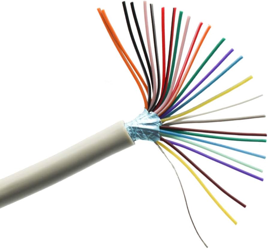
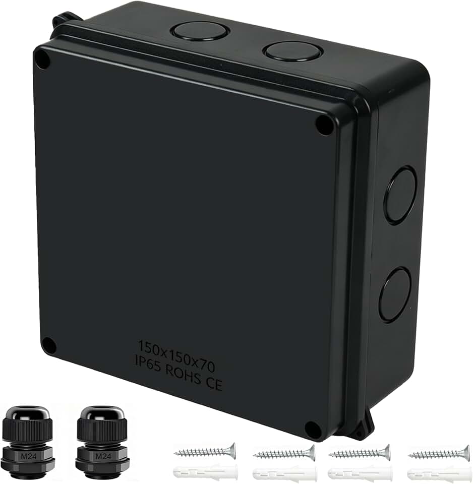
Installing the CE 65 encoder requires careful attention to mechanical mounting and electrical wiring to ensure reliable data transmission in industrial automation environments. The encoder’s IP65 rating protects against dust and water jets, but proper installation is necessary to maintain this protection. Follow the sequence below to mount the encoder and connect the power and data cables according to DIN 19258 standards.
As an Amazon Associate, we may earn from qualifying purchases.
Configure Controller Parameters
Input the encoder’s physical specifications into your PLC or controller software to ensure accurate position tracking. The CE 65 encoder supports a 25-bit capacity, allowing for 4,096 absolute revolutions. This high resolution prevents position loss during long machine cycles or multi-revolution applications.
Follow this sequence to enter the correct parameters in your controller software.
Test and troubleshoot signals
Before committing the CE 65 encoder to production, verify that it transmits clean data and responds correctly to commands. This phase isolates wiring errors, configuration mismatches, and environmental noise before they cause downtime.
Verify physical connections
Start with the cabling. Check that the shield is grounded at the controller end only to prevent ground loops. Ensure the connector is fully seated and the locking mechanism is engaged. Loose connections are the most common source of intermittent signal loss.
Validate data transmission
Connect the encoder to your PLC or motion controller. Enable the diagnostic interface or use a dedicated test tool to monitor the output. Look for consistent position values and stable communication cycles. If the data fluctuates, check the baud rate and protocol settings against the encoder's configuration.
Isolate noise and interference
High-voltage cables running parallel to encoder signals can induce noise. Maintain a minimum separation distance or use shielded twisted-pair cables. If you observe erratic behavior, test the system with the shield disconnected at the encoder end to see if the noise source is external.
Resolve common errors
When issues arise, consult the error codes to narrow down the problem. The table below maps common symptoms to their likely causes and fixes.
| Symptom | Likely Cause | Solution |
|---|---|---|
| No signal | Power or wiring fault | Check voltage and cable continuity |
| Erratic position | Ground loop or noise | Ground shield at controller end only |
| Communication timeout | Baud rate mismatch | Align PLC and encoder settings |
| Incorrect zero point | Mechanical misalignment | Re-calibrate during installation |
Confirm stability
Run the system through its full range of motion. Monitor the signal for drops or spikes. If the encoder holds its position and responds instantly to commands, the installation is successful.
No comments yet. Be the first to share your thoughts!